In Search of the Fell Mountain Railway- Part one " In the Goyt Valley"
As faithful readers of these blogs may have noticed we do like a story which connects Buxton and the High Peak with Italy. This one is a bit tangential but there is a connection between the Goyt Valley and Mont Cenis in Italy. It is also the story of a rather eccentric British invention and what ( with the benefit of hindsight) was a fairly ill judged idea to build a railway across the alps, while everybody else was starting to bore tunnels through them. So the Fell Experimental site involves an innovative British engineer and the adventures of British Railway engineers in Italy, it proved interesting to look into and well worth retelling. Classicists and archaeologists have for several centuries been discussing whether the Carthaginian general Hannibal used the Mont Cenis Pass to cross from France into Italy with his elephants. This has usually been based on fragmented and not very accurate descriptions passed down by Roman historian Polybius and Livy and involves quite a high degree of speculation. Trying to locate the exact site of the Fell Experimental Railway, somewhere in the Goyt Valley has felt pretty much the same.
The Derbyshire Historic Environment Record ( Monument record MDR170) discusses the site of the Experimental railway at “ Hartington Upper Quarter SK 0245 7524 : Goyt, Experimental Railway (site of); Fell: [SK 01707591 through SK 02177566 to SK 02457524], between Whaley Bridge and Buxton. The course of J.B. Fell's experimental railway, in use between 1863 and 1865, used to test a train designed for a mountain railway to link Lyons and Milan. It was the earliest self-propelled mountain railway. [Plan - see AO/61/106/8] . Fell's experimental engine, 'The Alpine', is referred to in 'The Diary of John Warren of Whaley Bridge (24 August 1863). Fell called the track the Rockland Incline. . There are no surface indication of this railway. Track of first mountain railway laid by Thomas Brassey and J.B. Fell, between 1863 and 1865, for experiments on steep gradients and sharp curves. Documentary sources indicate that between 1863 and 1865 experiments were carried out by Mr Fell while designing the first alpine self-propelled railway from Lyons to Milan. The site of this railway is unclear. There are no positive indications that a postulated course is correct. It seems unlikely to have existed here, as the hollow-ways are too narrow and/or uneven to have had a rail line laid along them. An experimental incline was identified in 1994. This incline is likely to be 19th century in date. It is a carefully built inline, with a flat bed and consistent gradient, thus almost certainly a railway feature. However, its design seems unlikely to fill Fell's criteria for his experiments. Therefore this feature probably dates from immediately prior to the building of the main Cromford and High Peak Incline in the late 1820s. ”
This short description of the Experimental Site does not really do justice to its place in the history of European railways. In the middle of the 19th Century Railway networks developed rapidly in France and Italy, but the Alps remained an impenetrable barrier to linking the two networks. In the 1850s , the County of Savoy on the French side of the Alps was still part of the Kingdom of Sardinia , and linking the two parts of the Kingdom became a strong political consideration for the Italians., The British had a rather more pragmatic commercial reason for linking the two networks, to speed up the Indian mail. A link from Paris to Italy across the Alps would connect to the Italian Railway network running to the southern Italian port of Brindisi with its relatively short sailing times to the Middle East. Different motives but a similar goal.
In 1851, the British entrepreneur and railway engineer Charles Henfrey had scoped out plans for a railway from Turin, which was then the capital of the Kingdom of Sardinia to Susa, the city which guarded the entrance to the Italian side of the Mont Cenis Pass. In June 1852 , the Kingdom of Sardinia voted to award the concession to construct this line to a joint venture company , Jackson Brassey, Henfrey . Henfrey had sent the final project to the Ministry of the Interior in Turin , offering to build it if the Government would provide half of the necessary capital and take over the operation, obtaining 50% of the gross income as consideration. He undertook to complete the work within two years of the legislative sanction of the project and asked to be able to use the Turin station. The Ministry complained that the station of Susa was too far from the city, seriously inconveniencing travellers, however with the construction of an alpine tunnel, Susa would cease to be an important node anyway. A request by the Municipality of Rivoli to be touched by the railway was declared unacceptable by the Ministry because, in addition to lengthening the route of the railway, it would have produced serious difficulties in construction increasing the expense and danger in operation. On April 13, 1852, an Italian contractor Celestino Ferroggio offered to carry out the road for only L. 5,900,000; while Jackson, Brassey, Henfrey asked for 6,270,000 lire. Although the bid was higher the Minister advised Parliament to vote for the concession to Jackson, Brassey, Henfrey having greater confidence in their track record.
Back to John Fell, who was working for Brassey in Italy at the time and in order to get to England would have taken the mail coach or diligence on the road which passed over the Mont Cenis pass. These regular trips may have inspired Fell to dream of a railway through the pass. While Mont Cenis may not have had the same note as say the Great St Bernard Pass, it had certainly played a part in European history. It now seems fairly sure that Hannibal did not use the Mont Cenis pass to invade Italy with his elephants, but Charlemagne and the Franks probably used that route to invade and conquer the Lombards, and in 1794 the French used the same route to invade Italy. Napoleon then had the rather spectacular road through the pass constructed. The Napoleonic road was wide and well-constructed , and on his travels Fell may have noted the a narrow gauge single track railway would have fitted along the edge of the road, without requiring huge amounts of costly engineering work. The problem was the gradients , horses or marching men were capable of going up far steeper gradients than locomotives. The gradients along the many hairpins of the Mont Cenis road were as high as 1in 12 or 1 in 14 in places
This gradient business becomes important in looking at the Fell railway. For the mathematically challenged amongst us , 1 in infinity is flat, most early British railways were designed for a gradient of 1 in 1320 (0.07575% ), higher gradients required extra locomotives or pulley systems to get up and down. Particularly noteworthy was the unreliability of early railway brakes on the downhill sections.
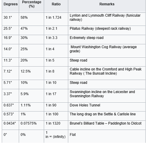
Broadly misspeak normal "adhesion" railways are struggling above 1 in 20, needing assistance from cables, before they give wat to cog railways and finally funiculars in steeper mountain stretches.
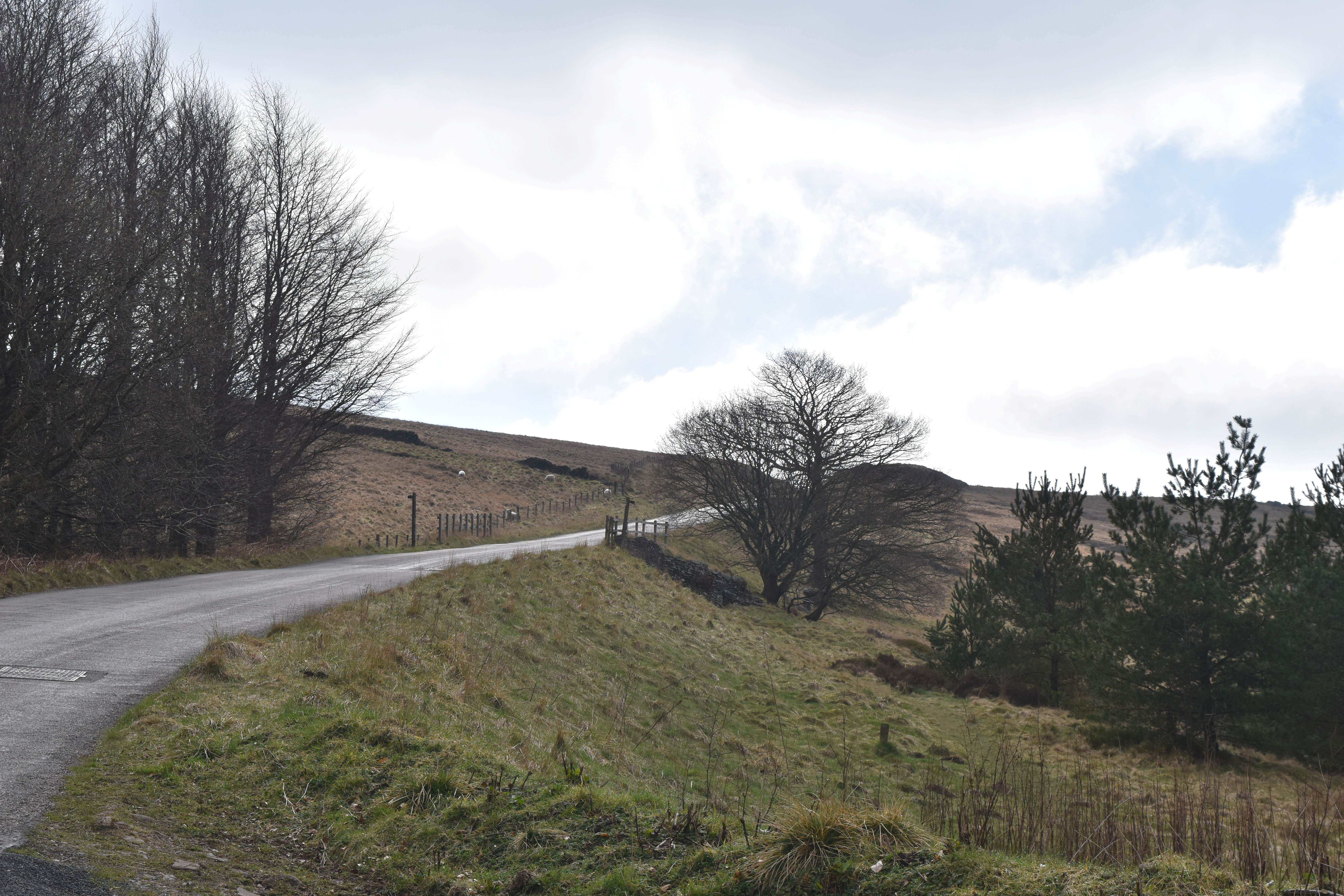
The Bunsall Incline on the Cromford & High Peak Railway, a 1 in 8 gradient which required a cable to haul the engine up
Meanwhile the French and Italians were planning a tunnel through the Alps,. In Savoy, the Victor Emmanuel Railway, ran from Culoz to Modane on the French side of the Alps with Henfrey’s railway running from Turin to Susa in Piedmont, and the Mont Cenis pass inconveniently in the middle. The Fréjus Tunnel was recognised as being the primary engineering challenge of a Turin–Modane railway; the projected length of its gallery was 12.8 kilometres which was twice as much as the previously longest tunnel in the world at that time. The Savoyard civil engineer Germain Sommeiller was appointed to head this undertaking. Considerable backing for the endeavour was forthcoming from individual Italians, not only in terms of funding, but also technical expertise, public endorsements, and labourers. During August 1857, drilling work commenced on the Bardonecchia side; activity started on the Modane side in December 1857. It had been deemed impossible to increase the rate of excavation via intermediate shafts, thus the tunnel was driven entirely from either end. Serious challenges were encountered, including difficulty with providing sufficient ventilation. New methods of ventilation were successfully introduced, alongside other technological innovations. At the time, it was believed that, if the tunnel's construction had to rely upon traditional methods alone, it would have taken 71 years to complete. Three years after the start of the tunnel's construction, in 1860 the Treaty of Turin transferred Savoy to France , although the change of borders did not greatly disrupt the rate of work on the tunnel.
Due to the estimated construction time of the Mont Cenis tunnel , a temporary railway over the mountain was proposed, by a number of British contractors, engineers and investors to obtain permission from the two governments to build the railway. By using the existing road as much as possible, costs could be kept low. What was needed was a way of getting the trains up and down without using several locomotives or pullies and John Barraclough Fell's system was seen as the solution.
On 26 January 1863, Fell filed a patent application for “improvement in working railway engines and carriages on steep inclines.” Patent number 3182 was granted on 16 December 1863. The Mechanic’s Magazine of 11 September 1863 reported on the details of the patent, complete with diagram.
“. The object of these improvements is to enable locomotive engines and carriages to travel up and down steep inclines with facility and security. For this purpose the patentee applies too the engines and carriages, wheels in pairs or sets of two or more, so arranged as to work on either side of a central rail, and to press and hold on such rail with a pressure and holding adapted to the circumstances of each case. In travelling up inclines the wheels of each pair or set are worked by the engine at speed and with a pressure on each side of the central rail according to the load and the rate at which the engine has to travel, and the adhesion necessary for taking the load up the incline. In descending the inclines these pairs of wheels on the engine and carriages are employed as brakes, with an adhesion adapted to the load. These pairs of wheels also hold on either side of the central rail,, in such manner as to afford a great amount of security against the wheels of the engines or carriages jumping and getting off the lines on which they are travelling. In the accompanying drawings, figs 1 and 2 represent the plan and end elevation of a locomotive engine, which independently of the ordinary bearing and driving wheels , is furnished with two or more horizontal wheels D,D pressing against the central rail E. The wheels D, D are driven by two additional steam cylinders G, G as shown by the plan fig, 1 A transverse shaft K is provided with a right and left-handed screw , which being acted upon by the wheels M,M draws together the springs N,N, by means of which the horizontal wheels are made to press upon the central rail; , and so obtain the amount of adhesion required. Horizontal wheels may be also attached to the carriages and waggons , and constitute so many brakes. For the descent of steep inclines the horizontal wheels of the engines may be reversed, in order to check the speed , or to secure the immediate stoppage of the train. The additional adhesion wheels , shown in figs. 1 and 2 in a horizontal position may, if preferred , be placed at an angle of 45 deg., or less , and may have their tyres cylindrical or grooved. In order to avoid friction in a vertical direction between the wheels and the central rail; resulting from the movement of the engine on the springs which support it , these wheels may be so fixed on the axles as to allow them whatever vertical play may be needful. The pressure of the horizontal adhesion wheels upon the rail on which they work may be produced by means of a steam cylinder , or by water pressure , or by the use of springs of any convenient form
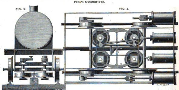
The design for Fell's Central Rail System
In theory Fell’s patent third rail would solve the problem of the higher gradients on Mont Cenis but having obtained his patent, Mr. Fell then needed to test his railway in practice. The tests took place in the High Peak, near Whaley Bridge. The Manchester Examiner reported (and this report seems to have been syndicated in various local newspapers )
“Trial of An Alpine Locomotive at Whaley Bridge
An interesting trial of a locomotive engine , built upon novel principles at the Canada Works, Birkenhead, took place on Tuesday at Whaley Bridge , on the Cromford and High Peal railway , and upon a short line made specifically for the experiment. The engine is constructed to ascend and descend steep gradients, to pass sharp curves, and to perform work which locomotives as yet have never been able to accomplish. The inventor and patentee, Mr. J. B Fell, has gone upon the principle of obtaining increased adhesion without increase in weight. In the centre of the carriage way a raised rail. considerably larger than on ordinary lines is laid down and the engine and carriages are fitted with well lubricated horizontal wheels, which by pressing on either side of the centre rail , produces the adhesion necessary for working up sharp inclines. The practical object of this invention cannot but be greatly interesting inasmuch as it proposes to run a line of railway for passengers, mails and merchandise , over the very heart of the alps , and along a road hitherto considered impassable for locomotives, It is the well-known military road hewn out of such difficulties by the First Napoleon that it is thus contemplated to traverse. At present there is a tract of mountain pass forty -eight miles in length between the two great railway systems of France and Italy, the terminus of the former being San Michel in Savoy , and the latter Suse, in Piedmont. The Mont Cenis by which this district is known , has been considered so important for purposes of traffic that the French and Italian governments give years ago commenced the excavation of a tunnel , to remove the difficulties so often felt. At the lowest computation this great undertaking will take twelve years to complete. The proposed railways over the surface of the pass will only ne two years in the making , and the projectors would therefore have ten years of working before the tunnel was available for traffic. . The district has been thoroughly surveyed by Mr. Fell, in connection with a company of week known English capitalists and contractors , and the scheme has met with the approbation of the Italian Government . The present road is sufficiently wide to accommodate the railway , and leave room for local traffic , and the usual engineering labours, tunnelling etc. will not be required. The chief difficulty however is that which the new locomotive is especially designed to overcome , namely the excessive steepness. Starting from San. Michel, the road gradually rises as the villafe of Lanzlenourg . whence it makes a rapid ascent with gradirnts of 1 in 12 , to the summit of the pass, which is 7,000 feet above the level of the sea. From this point there is an equally rapid descent to Suse. In addition to this rising and falling there are frequent sharp curves. It is proposed to cover those portions of the line where it is known that avalanches and snowdrifts fall. The locomotive to be employed here is , in fact , a double engine a horizontal and vertical engine combine, and so arranged that it may be worked either together or separate according to the steepness of the incline . Not the least feature of this invention is the safety which it ensures. The horizontal wheels referred to above facilitate the passage of curves ,enable the driver to stop the engine in the middle of the steepest gradient , give a propulsive pressure of several tons , and, by means of the flanges which underlap the entire rail, renders it nearly impossible that the carriage can be overturned. The brakes are extremely powerful , and as they are attached to each carriage , no danger can arise from a coupling chain giving way. The extreme narrowness of the gauge renders the curves less difficult to [pass , gives more room for the public road , and greatly assists for erecting the covered ways for the more dangerous parts, The trials on Tuesday were in every way successful , and for once the high peak proved an aid rather than an obstruction to the engineer. There were two inclines the first being two hundred yards long, a a gradient of 1 in 13, and the other 550 yards long at a gradient of 1 in 12, with curves of about two chains radius (.This represents the most difficult part of the Mont Cenis road. The shortness of the line on which the experiment was was made prevented the full getting up of steam , and the trial may, therefore, be taken as a fair test. The locomotive itself, weighing 16 tons but with a tractive force of 32 tons first ascended and then descended the lines, stopping in the middle , and going backwards and forwards as required with perfect ease. Four wagons lade with 26 tons of ballast, were then attached and the experiment was repeated with equally satisfactory results. It is proposed to work the Mont Cenis line at the average speed of 12 miles, thus performing the journey in from four to five hours. The number of passengers will not exceed 100, equivalent to 24 tons Within the last week many of the principle engineers of the country have witnessed these experiments under the direction of Mr. Fell, and the novelty of an engine and waggons running easily and safely up and down a hill which would make the most courageous “whip” look twice before he risked himself and his horses by venturing down , is beheld by crowds of gaping and awe struck rustics , who seem to doubt whether it is prudent or not to believe the evidence of their own eyes. The London and North western Railway Company have liberally given to Mr. Fell, the use of the line , and afforded other facilities for the trial; of the new locomotive , The trials will be continued today and tomorrow. “
A number of reports mention private tests followed by a public test attended by members of the engineering fraternity, specifically cavaliere Felice Biglia, the Chief Italian Civil Engineer and head of the Italian Railway Inspectorate representing the Italian Government and M, Desbriere of the Vittor Emanuel Railway for the French. The Italian and French observers were happy as to how Mr Fell’s system had worked as a proof of concept and the scene was set for a further more challenging test on Mont Cenis itself.
Contemporary accounts report the test as taking place at “Whaley Bridge on the Cromford and High Peak Railway, and upon a short stretch made especially for the experiment” or “applied it to an experimental line on the High Peak and Cromford branch of the London and North Western Railway” . The Cromford and High Peak Railway (C&HPR) was a standard-gauge line between the Cromford Canal Wharf at High Peak Junction and the Peak Forest Canal at Whaley Bridge. The railway, which was completed in 1831, was built to carry minerals and goods through the hilly rural terrain of the Peak District .The railway was in commercial operation in 1863, making it implausible the Fell’s experiment was conducted on the C& HPR line itself and furthermore the C& HPR was a standard gauge of 4ft 8 inches, while the experimental track had a gauge of 3ft 6inches. However the CHPR did run along the Goyt Valley to the location where the trial took place.
The test is site is described as the track having a gauge of 3 ft 6 in. and the length about 800 yards, of which about three fourths were on sharp curves and on gradients of 1 in 12 to 1 in 13 .The 800 yards was divided into two separate test sites, the first of 200 yards on a 1 in 12 gradient and the second of 550 yards in a 1 in 13 gradient, There is also the information of the radius of the curves being 2 chains (44 yards). There is also the interesting question of how they managed to get a 16 ton locomotive from Birkenhead to the High Peak, and then move it on to the two short test tracks, which unfortunately none of the newspaper reports fail to mention. So based on the documentary evidence we are looking for
- Two curved stretches of track – the first around 200 yards in length , the second around 550 yards in length
- The radius of the curves should be around 44yds
- They should be on as gradient of 1 in 12
- Possibly adjacent to the C& HP Railway
- Possibly passing under the Bunsal Incline
- Near enough to be able to move a 16 ton locomotive and the ballast waggons without too much of an effort
Armed with these facts in summer of 1961, Mr Houlton went to the Goyt Valley in search of the Fell Experimental site. he puvlished an article basd on his findings in railway wotld.
“ As there appears to be no record of this historic track, a detailed description might be useful. Two miles from Buxton on the main road to Manchester ( A6) , Goyt Lane runs over Long Hill down to the Goyt Valley -The line of the track is shown on the Ordnance survey map as a sickle with the handle towards this lane. An initial easterly curve is, however , omitted from the map , for almost all on the 1,300 foot contour, by a gap in the gritstone wall on the right of the lane is an artificial mound. It is some 200 yd east of the track end on the map and appears to be the upper railhead of Fell’s trial mountain railway.
… The descent begins through a shallow cutting obviously designed for thew width of the rail track. It was 3ft 7 ½ in. gauge, with the central rail set on longitudinal timbers and raised 7 ½ in. above the top of the outer rails. The formation curves to avoid what is often damp ground, marked by rushes and the turns sharply north. With a gentle downward gradient and one slight curve, it continues across the moor making to a modern grey stone wall built across it. Especially when the sun is on it, the line of the two outside rails is here clearly traceable in the grass growth-The wall dis across the track 20 yd east of the gate opening.
On the north side of the wall , the track continues slightly below the moor level, pausing on the right of a small excavation. The down gradient now increases and the track makes toward a shallow cutting on the edge of the moor. The grass lines indicating the position of the rails here are distinctly visible , and then they make a sudden sharp curve almost a right- angle to the east This is the first pry of the vicious S bend which would be a stiff test for the train. It is near the edge of a stone cliff dropping steeply to the Bunsal stream. Again there are excavations to the tight of the track . The S-Bend is completed with a sharp turn to the west , and the formation here much wider proceeds steeply downhill in a gentle curve.
An artificial embankment rises on the left and its south side are signs of an earlier track. The s- bend appears to have been made more acute. Ahead down the slope is the now abandoned way of the Cromford & High Peak Railway going up the hill side with a gradient of 1 in 7 . This was worked by a stationery engine , and was dismantled in 1892. Fell’s line goes under Bunsal incline through a grey stone tunnel bridge”.
So what happens to the railway after the tunnel. Mr Houlton wrote the following
“West of the tunnel are the remains of a stone building < the hand/made roof slates are stacked in neat rows. On the right is the steep sided hillock, Bunsal Cob , and the track , now more like a lane , makes its sickle curve round the western slope / From the flat top of the hill .Fell and Brassey probably often watched their prototype train going up pr down the moorland slope beyond the tunnel, discussing its performance and considering readjustment.
Bunsal Farm, demolished when Fernilee Reservoir filled the Goyt Valley below was noth/west of the cob, and the line of the track is less obvious until about twenty five years ago, this part was inhabited and farmed. A spring and trough here would provide water for the engine , and here ould also be a junction link with the Cromford and High Peak . The way [possibly continued over the incline on the fine stone bridge. Alternatively , it may have made a right handled curve and then descended by the present line of sycamores to the stream for water a little to the north of the modern white footpath suspension bridge . it is even possible that the Goyt stream was bridged , as a turf way was clearly visible over the gey caked mud when the upper part of the reservoir dried up in the drought of 1959. “
In March of 2025, Alan Roberts and myself went down to the Goyt Valley to have a look around. The tunnel described by Houlton is fairly easy to find. I should have taken a measure, but as can be seen from the photo, it looks wide enough to fit a 3ft 7 inch rail. The roof looks low, but I imagine that there has been an accumulation of earth at the bottom. It seems that this should be the tunnel referred to by Mr Houlton. From the tunnel a track proceeds up the hillside, it is clearly a track approximately three to four feet wide and the curves described by Mr Houlton are visible. It all definitely looks manmade. The track proceeds uphill round these manmade curves for several hundred yards as described by Mr Houlton.
At the time we made the trip , we had not yet obtained a copy of his article, so I did not procced all the way. On the other side of the tunnel , Mr Houlton’s explanation also seems convincing also. He had the advantage of being in the Goyt Vallet in 1961, before the Erwood Reservoir was built and the landscape has changed considerably. Since then Bunsal Cob has been covered in trees and on the other side is the Erwood sailing club and car park, With the land now wooded it is difficult to see any tracks. But having looked at the types of curves on Monr Cenis ( see part 2 ) his description of a curve around the bottom of Bunsal Cob and back to the C&HPR seems convincing.
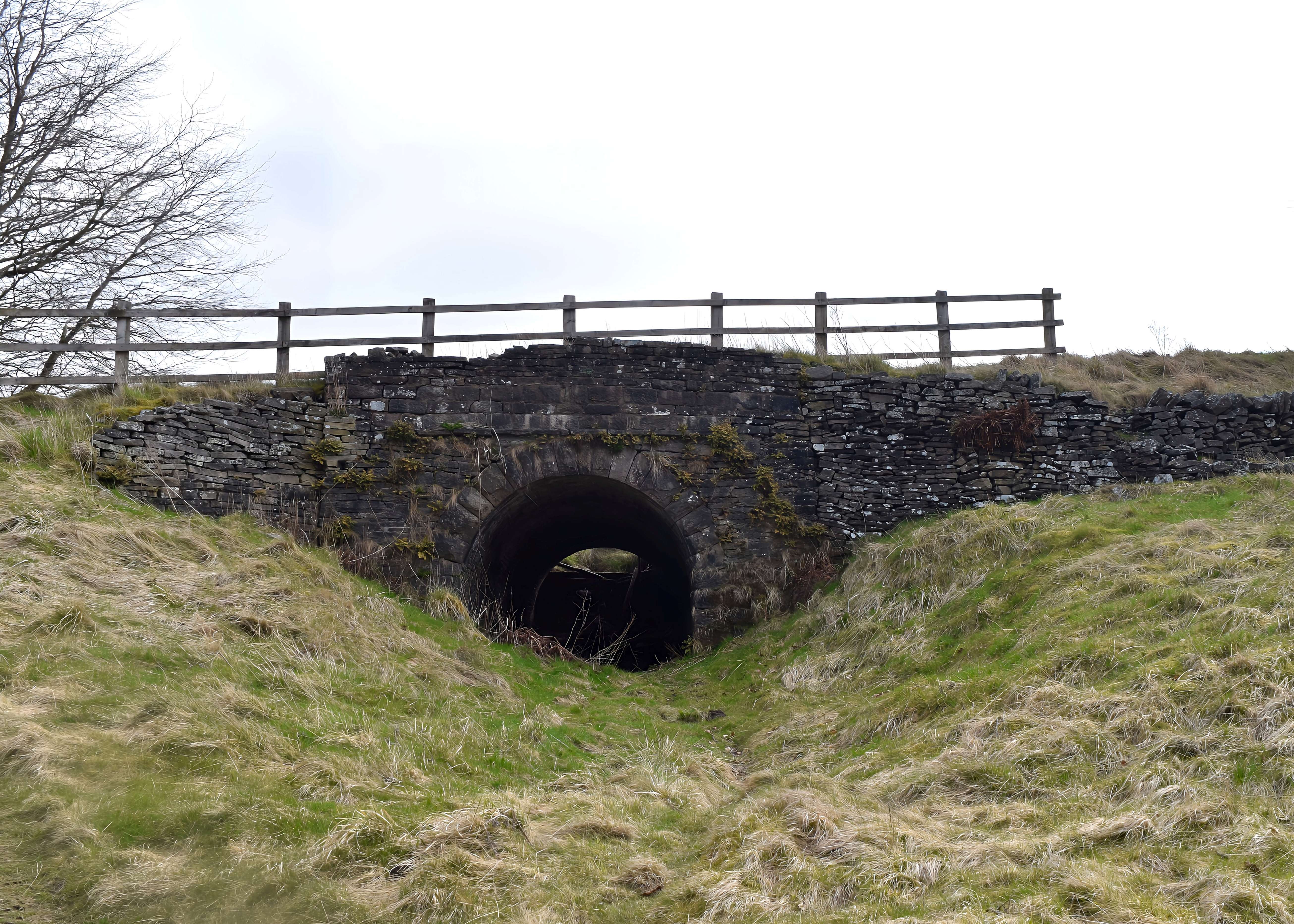
."Fell’s line goes under Bunsal incline through a grey stone tunnel bridge”.
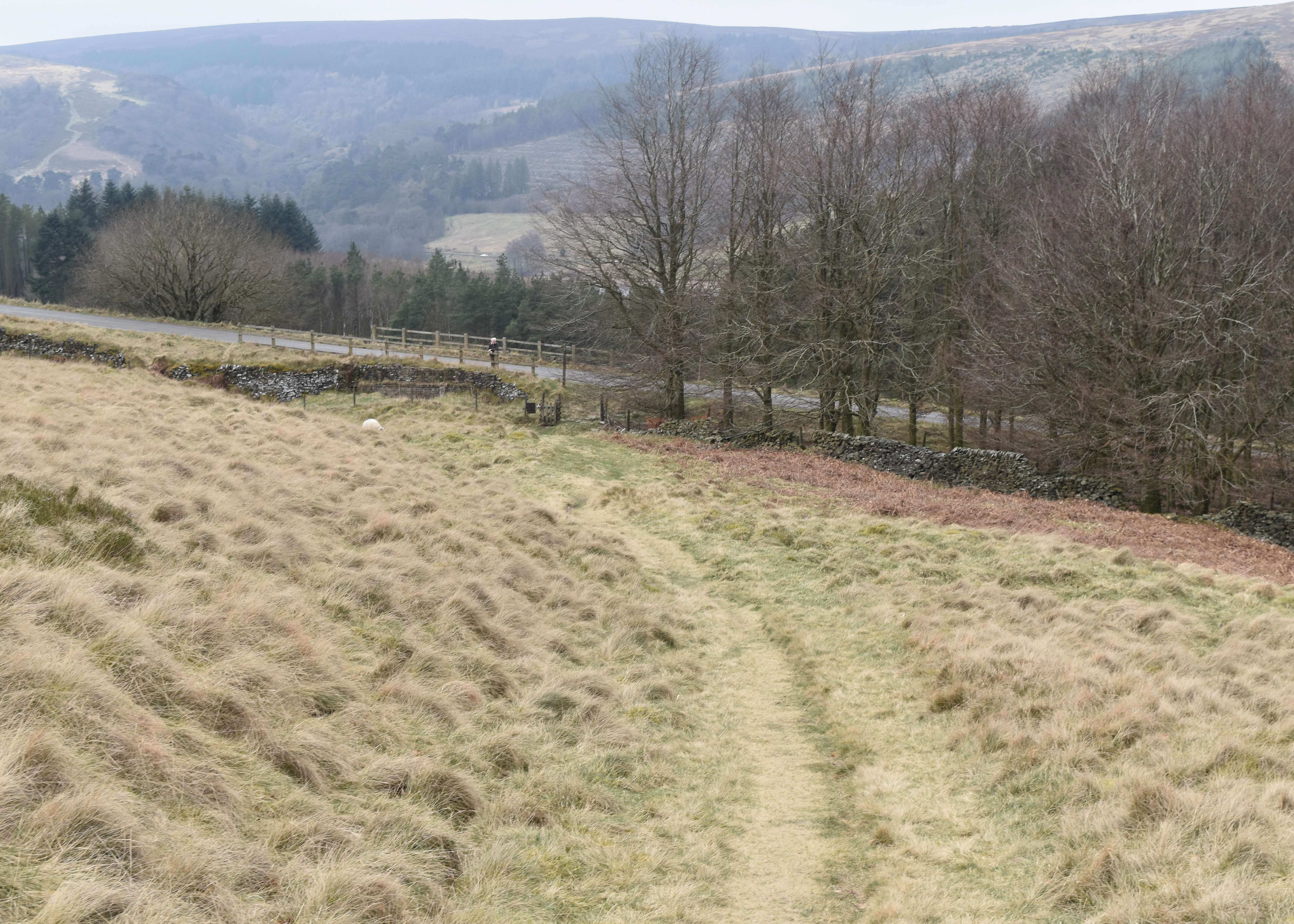
Looking down towards the tunnel . An artificial embankment rises on the left and its south side are signs of an earlier track. The s- bend appears to have been made more acute. Ahead down the slope is the now abandoned way of the Cromford & High Peak Railway going up the hill side with a gradient of 1 in 7
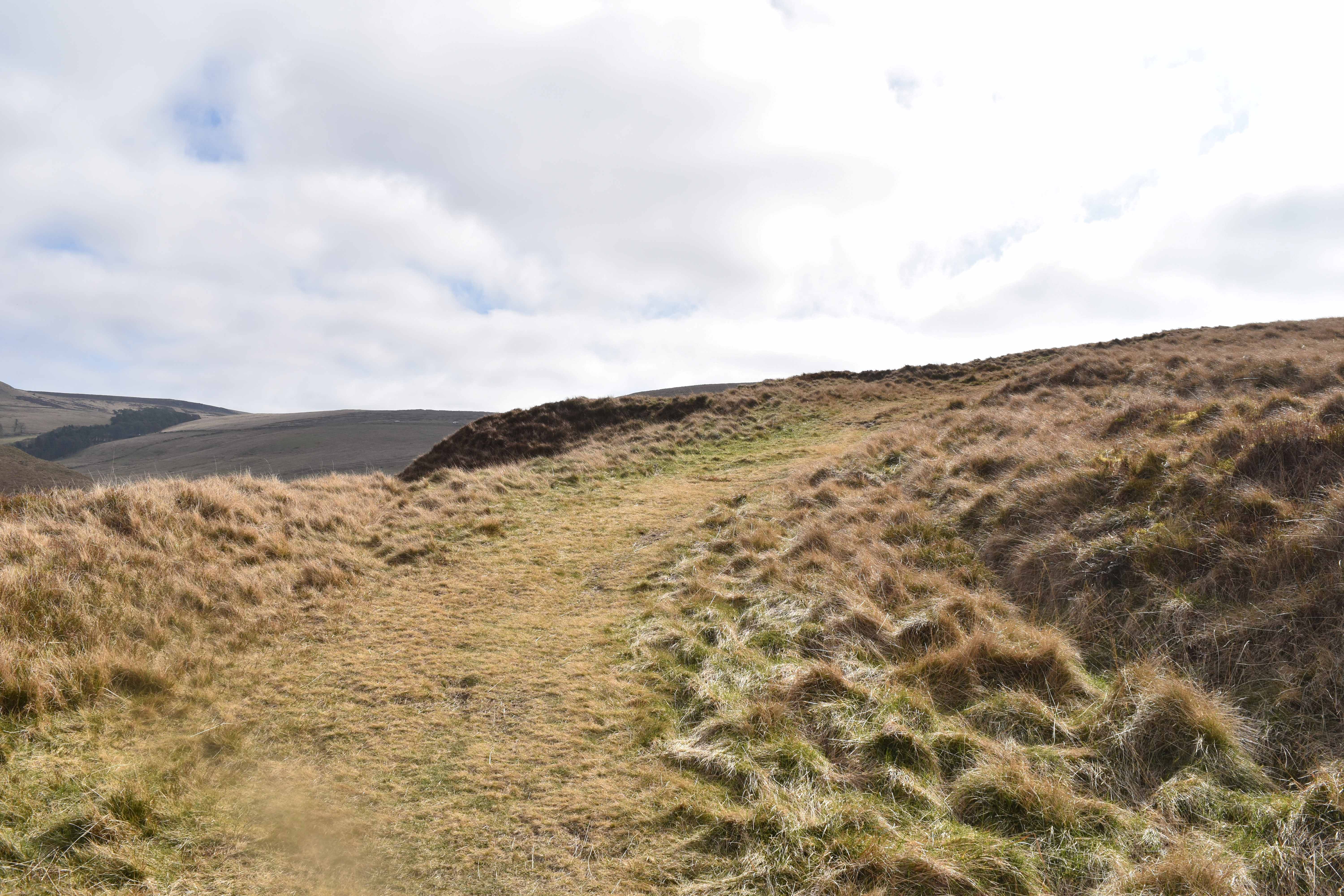
Looking up the hill from Bunsal Rise; "gradient now increases and the track makes toward a shallow cutting on the edge of the moor. The grass lines indicating the position of the rails here are distinctly visible , and then they make a sudden sharp curve almost a right- angle to the east This is the first part of the vicious S bend which would be a stiff test for the train. It is near the edge of a stone cliff dropping steeply to the Bunsal stream"
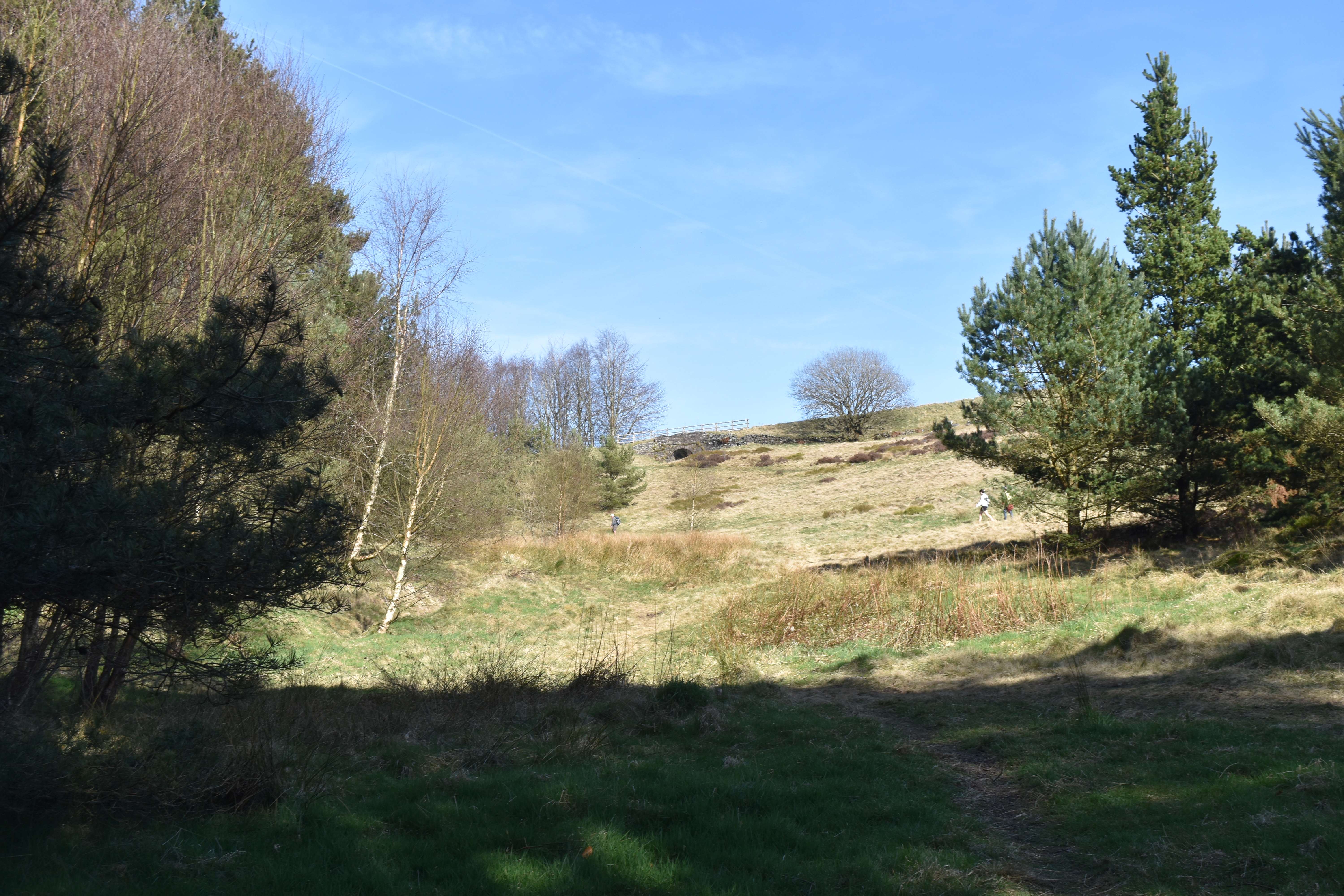
“West of the tunnel are the remains of a stone building, the handmade roof slates are stacked in neat rows. On the right is the steep sided hillock, Bunsal Cob , and the track , now more like a lane , makes its sickle curve round the western slope"
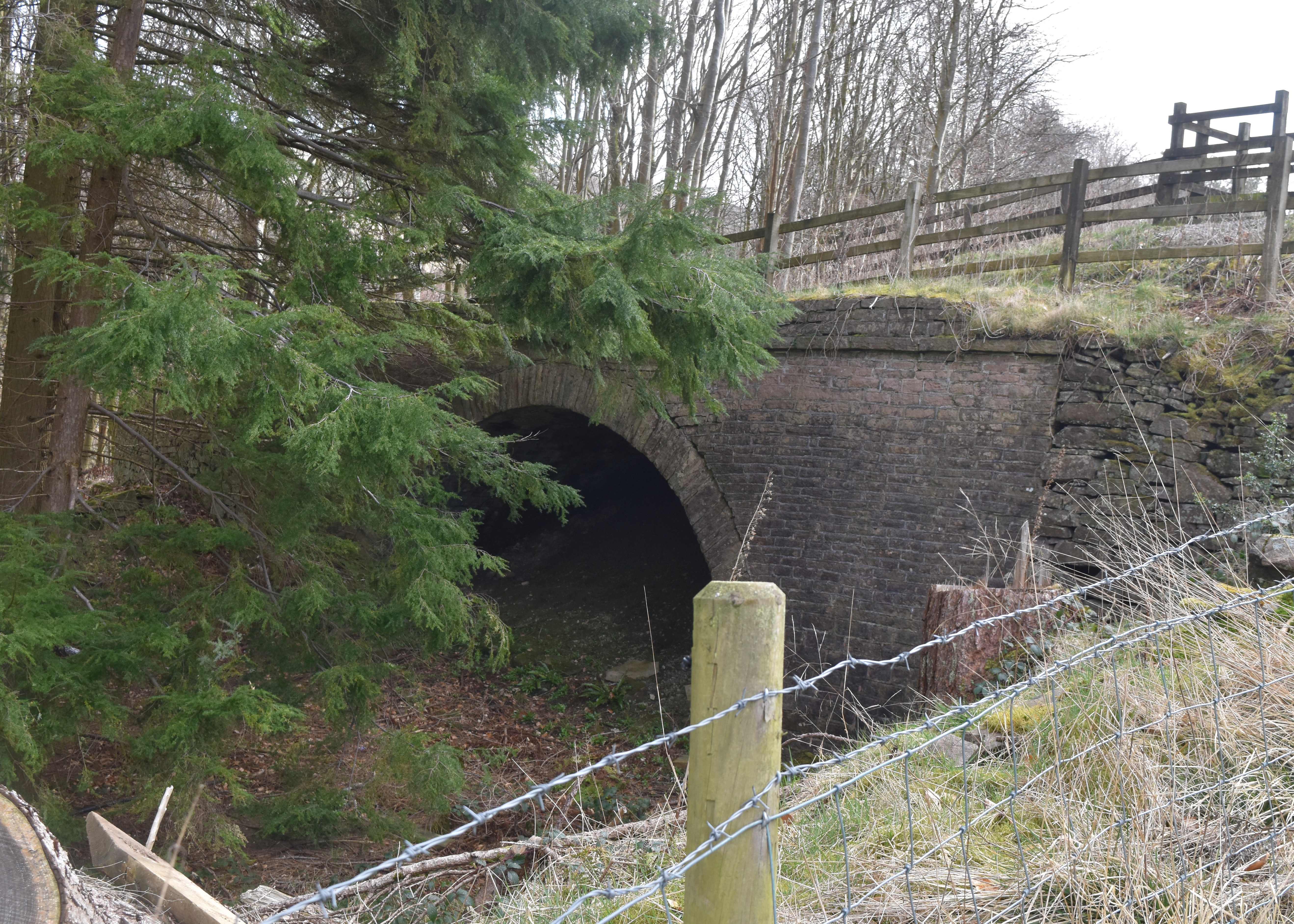
The way possibly continued over the incline on the fine stone bridge.
I realise that there is some risk of trying to force the description to fit the geography, but it al sounds rather convincing that this the right place. Back in 1961, Mr Houlton dis not have the benefit of Google Earth. Looking at the area in the photographs , the area in the screenshot from google Earth appears to fit the bill. Google now has a measuring function and the yellow line is in the region of 450 to 500 metes ling- so maybe ties in with that 550 yard stretch, The same stretch is visible on the Ordnance Survey , On the OS it also shows a Ford and other streams beyond the track. The whole thing is the S or Sickel shape described by Mr Houlton. Furthermore looking at the photos, the track has a consistent width. Again should have had the measuring tape. But by eye , it s looking between 3 foot and four feet.

Mr Houlton's Map
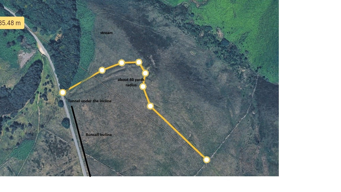
Our route as seen from Google Earth
Maybe some more accurate mapping might be useful. It is also puzzling that some of the newspaper articles’ refer to two separate test tracks, but logically they must have been connected. Mr Hoult’s location seems convincing, he offers further supporting evidence, such as the nearby presence of coal and water , and the Fell’s ability to acquire surplus track from the Miller’s Dale railway for his construction. Since the railway was removed after the tests, there is unlikely to be any other physical evidence Mr Hoult’s suggested location seems to be the best bet.
In part two, I head over to Mont Cenis to see if I can find any trace of the Fell Mountain Railway
Mr Houlton's article appeared in the 1961 edition of Railway World. i have been unable to locate him to ask the relevant permissions to quote